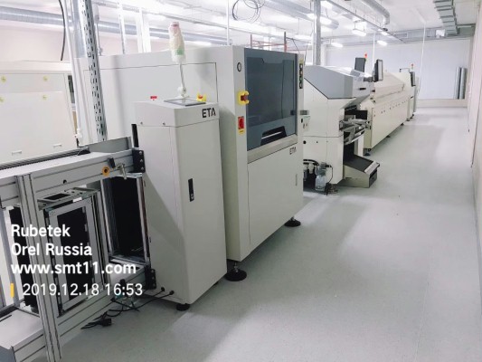
How to Program The PCB Chip Mounter
Quality pick and place machine, JUKI PCB chip mounter, JUKI SMD placement, with professional SMT line solution, oversea service and technical support.

The pick and place machine is a device used to place components at high speed and high precision. JUKI PCB chip mounter programming refers to placing a series of work instructions in a prescribed format or grammar, allowing the JUKI PCB chip shooter to perform placement work in a predetermined work mode. The JUKI PCB chip mounter programming is divided into two stages, namely the offline placement of the JUKI SMT placement. The second is the online debugging of the SMT pick and place equipment. Each factory has different details, depending on the model and management mode of the PCB pick & place machine.
On-line debugging of JUKI chip mounter:
1. Import the compiled program into the smt placement machine equipment.
2. Find the origin and make a mark.
3. Gradually correct the position number coordinates.
4. Optimize the save program, check the component direction and data again.
5. Turn on the patch panel to confirm.
The main information that must be needed before programming the placement machine is:
1. Placement information, including location number, coordinates, angle, etc. The customer will provide the corresponding BOM list, placement number drawings, samples, etc.
2. Material information, material number specifications and parameters.
3. Mark information, optical mark coordinates and parameters.
4. Link board information, how many boards are connected.
5. PCB information, such as length, width and thickness, to confirm whether it can be produced on the machine.
The offline preparation for placement machine programming is as follows:
1. Organize the BOM of the required patch product first, and the programming needs to be done on the computer, so it must be electronic. It is generally in excel format.
2. Extraction of coordinates. There are three situations:
(3) If there is only a copy of the BOM and the coordinates cannot be provided, a scanner is needed at this time. After scanning the PCB, save the points in the CAD format, and then combine the coordinates and the BOM. 3. After the BOM and the coordinates are combined, check whether there is any omission or Relocation, if necessary, the engineering department needs to contact the customer for confirmation, and save it in the format required by the machine after OK. These three steps, offline programming is almost complete.
(1) If it is the coordinates of the exported excel or txt file, it is enough to directly use the programming software to merge the coordinates with the organized BOM.
(2) If it is a PCB file, then you need to export the coordinates yourself. Generally, you can export it in excel format with protel99 or PADS2007.
❙ JUKI Chip Mounter Video